Quickstart Guide
This guide will help new users to quickly setup our QSBASE2 Linux Development Kit.
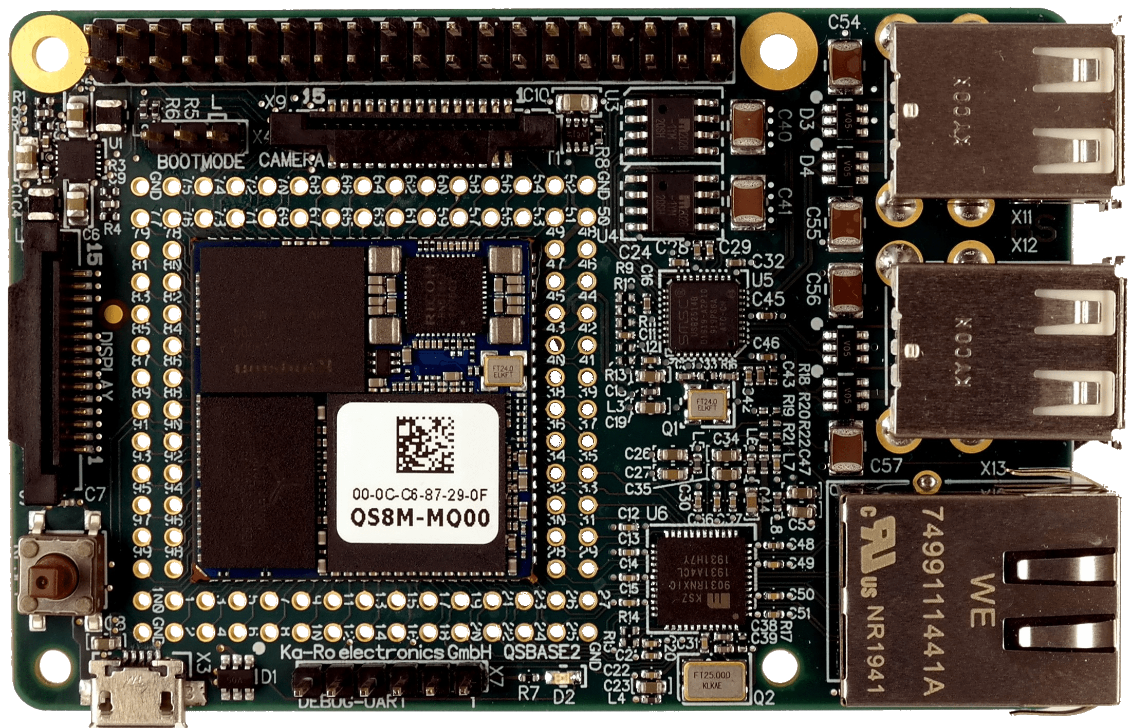
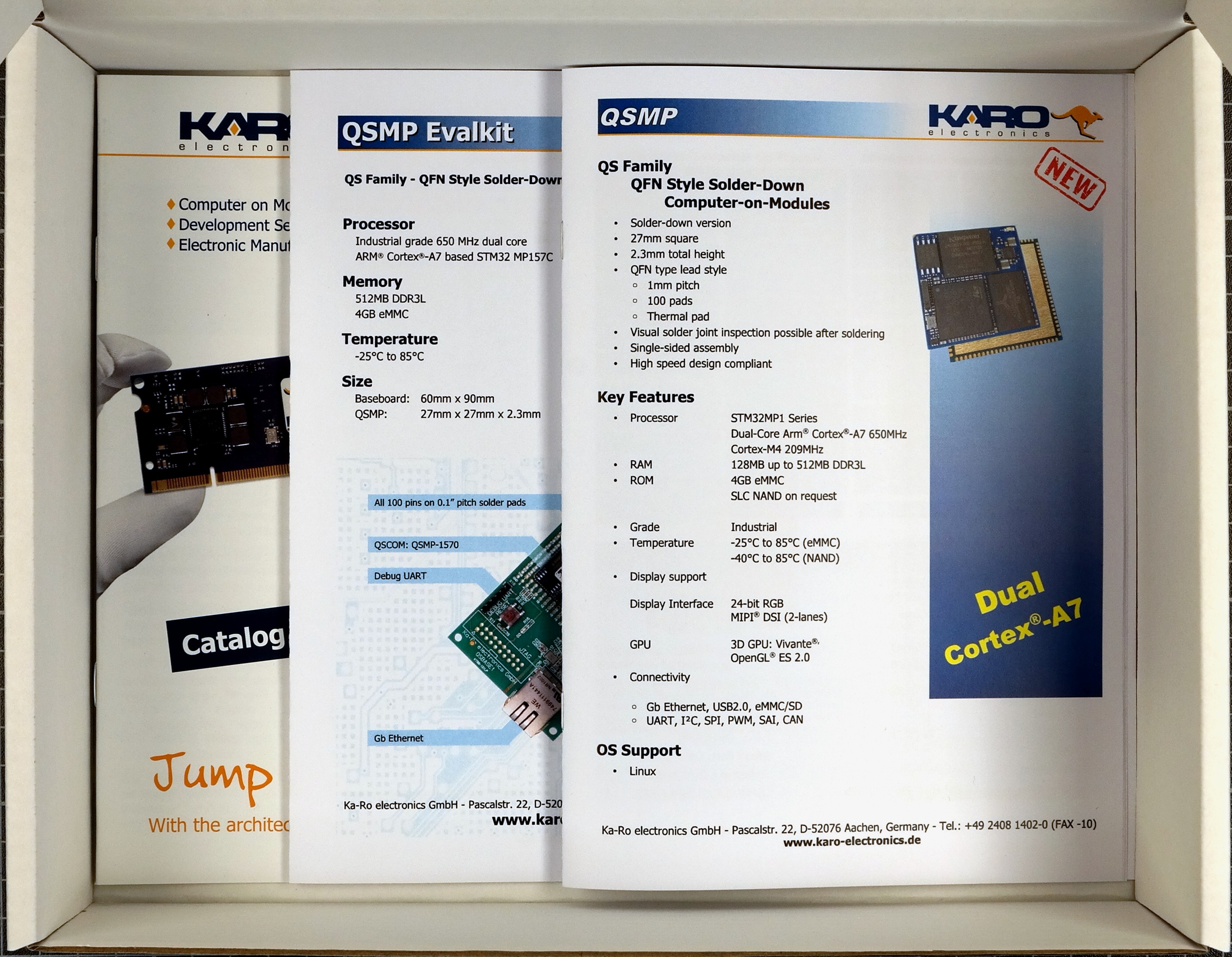
Detailed information about the QS solder-in module itself is available on our website.
Unboxing
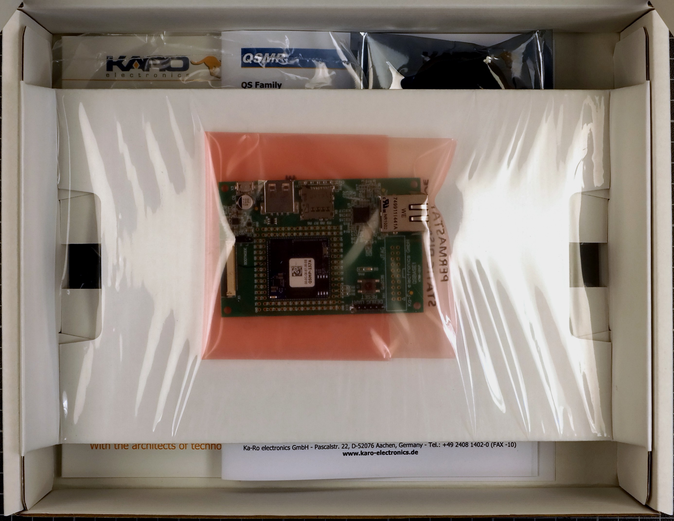
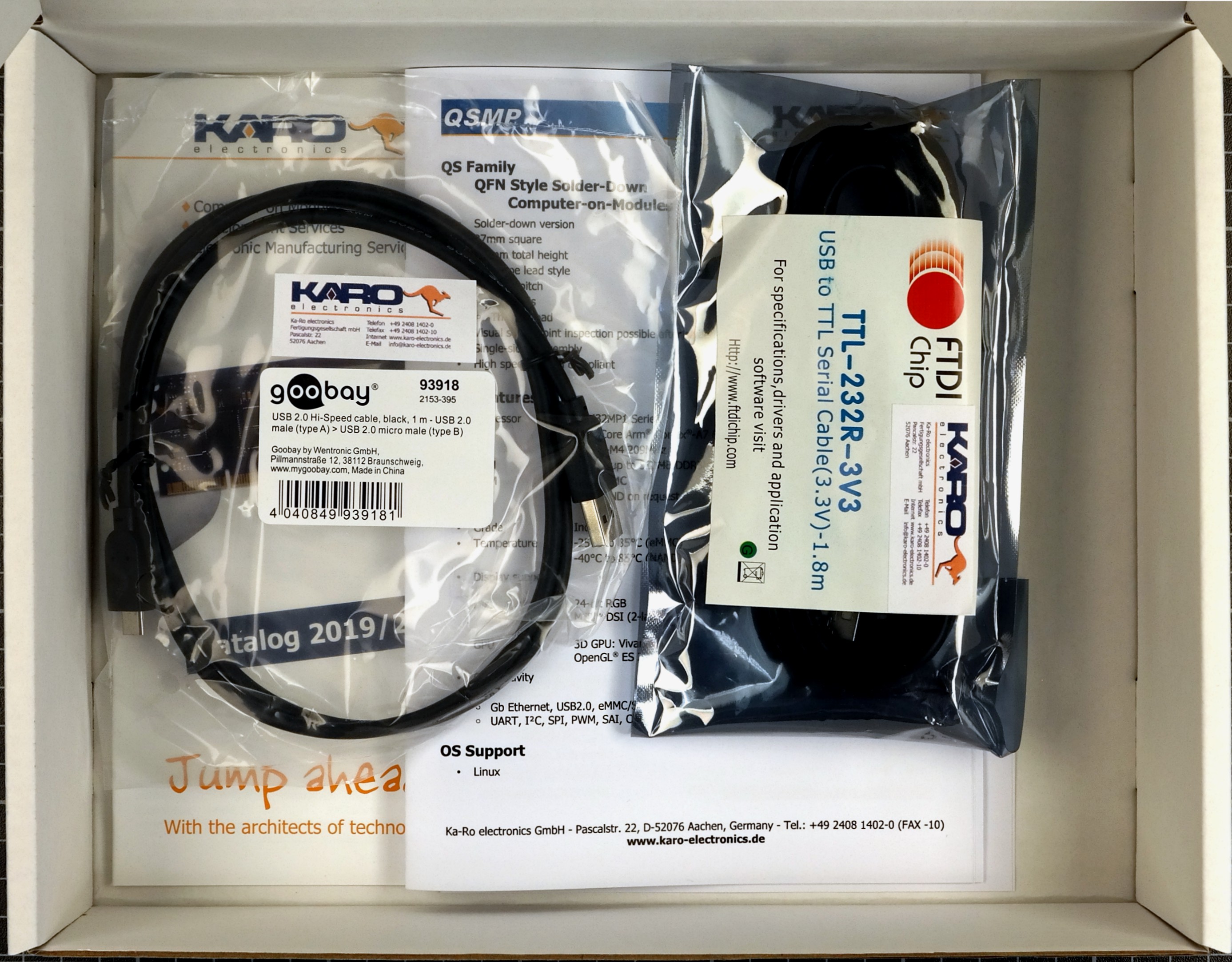
When opening the package of the Development Kit you should find the following components inside:
|
|
|
|
|
|
Wiring
Connect the QSBASE2 board as shown in the image below.
|
|
|

|

|

|
Booting
After connecting the micro USB your board will boot.
Your module is pre-programmed with our karo-image-minimal headless Linux.
Next Steps Usage
Topic |
Description |
|---|---|
Re-installing the OS |
|
Display support |
The QSBASE2 Development Kit supports the official Raspberry Pi 7inch Touch Display. The QSBASE2 can be mounted directly to the display. Tip The official Product Site of the Raspberry Pi 7inch Touch Display: https://www.raspberrypi.org/products/raspberry-pi-touch-display/ The sources supporting the Display are integrated our Yocto Layer. Refer to our Yocto Guide. We also provide a Ready To Use weston image to flash your QS module in our Download Area. 

|
Next Steps Software
Topic |
Description |
|---|---|
Linux Guide |
Go to: Software Documentation |
WiFi Guide |
To enable WiFi support. Go to: Software Documentation -> WiFi/BT Guide |
Camera Guide |
To enable camera support. Go to: Software Documentation -> Camera Guide |
Google Coral Edge TPU |
How to use Google Coral PCIe ML accelerator. Go to: Software Documentation -> Coral Edge TPU |
Machine Learning |
Using NPU and starting ML Demos. Go to: Software Documentation -> Machine Learning Guide |
QT5 Development |
Develop a QT5 app for your customers. Go to: Software Documentation -> QT Guide |
Electron Development |
Develop an Electron app for your customers. Go to: Software Documentation -> Electron Guide |
Customizing the BSP |
If you want to use our Yocto Layer, or want to create your own customized Linux distribution, have a look at our Yocto Guide. Go to: Yocto Guide |
Next Steps Hardware
Topic |
Description |
|---|---|
QSBASE2 Pinouts |
Connector pinouts can be found in the Hardware Documentation. Go to: Hardware Documentation -> Pinouts -> Pinout |
QS Developers Guide |
QS-Standard pinout, description and layout guidelines. Go to: Hardware Documentation -> QS-GUIDE |