USB

The QS Computer-on-Modules, such as QSMP and QS8M, contain two separate USB 2.0 compliant interfaces. High-speed USB operates at 480 Mb/s observing some basic rules or guidelines will usually guarantee successful operation.
VBUS
The QS modules does not include a signal for supplying the 5V VBUS power for USB. An external power management chip or discrete logic for enabling VBUS is required for the host operation. The power distribution circuit must have over-current detection capability to be compliant with the USB standard. There are no dedicated pins reserved for this in the QS standard. Use General Purpose Input/Output (GPIO) pads as OE (VBUS_EN) and OC (VBUS_OC) for the VBUS power distribution circuit. Some QS modules have pins with dedicated VBUS_EN (Output) and VBUS_OC (Input) alternate functions, e.g. QS8M pin 71 - USB1_OTG_PWR and pin 72 USB1_OTG_OC. Using these may interfere with the use other standard QS interfaces. A switch designed specifically for USB power, such as the Maxim MAX1931, or a general purpose power-distribution chip, such as Micrel’s MIC2026, can be used.
Note
The i.MX8M Nano processor has only one integrated port.
Pin |
Signal |
type |
I/O |
Requirements |
43 |
USB_VBUS_A |
5V |
IN |
Can be connected to VBUS directly |
44 |
USB_DN_A |
USB |
I/O |
Route USB differential signals with 90 Ω differential impedance |
45 |
USB_DP_A |
USB |
I/O |
|
46 |
USB_VBUS_B |
5V |
IN |
Can be connected to VBUS directly |
47 |
USB_DN_B |
USB |
I/O |
Route USB differential signals with 90 Ω differential impedance |
48 |
USB_DP_B |
USB |
I/O |
Wiring example
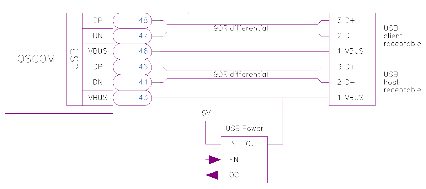
USB2.0 Design Recommendations
Parameter |
MIN |
TYP |
MAX |
Operating Speed |
240 MHz |
||
Signal Trace Length |
15 cm |
||
Differential Pair Skew |
5 ps |
||
Differential Trace Impedance |
81 Ω |
90 Ω |
99 Ω |
USB3 Super Speed

The QSXP provides a complete USB3.0 interface. To implement a USB Type-C interface (UFP, DFP, or DRP), external hardware must be added to manage the two configuration channel IOs (CC1 and CC2) as well as monitor the plug orientation and switch the single USB3 SS interface.
Route all USB differential signals with 90 Ω differential impedance.
Pin |
Signal |
Requirements |
25A |
USB_TXN |
|
26A |
USB_TXP |
|
50A |
USB_RXN |
|
51A |
USB_RXP |
USB3 Super Speed Design Recommendations
Parameter |
MIN |
TYP |
MAX |
Operating Speed |
2.5 GHz |
||
Signal Trace Length |
10 cm |
||
Differential Pair Skew |
1 ps |
||
RX/TX Skew |
1.6 ns |
||
Differential Trace Impedance |
85 Ω |
90 Ω |
95 Ω |
See also
Texas Instruments High-Speed Interface Layout Guidelines
QS Standard Contact Group Index
Pins |
Function |
Pins |
Function |
Pins |
Function |
Pins |
Function |
|---|---|---|---|---|---|---|---|
1-4 |
5-10 |
11-14 |
15-18 |
||||
19-35 |
36-42 |
43-48 |
49-52 |
||||
53-76 |
77-78 |
53-72 |
79-88 |
||||
89-96 |
97-100 |
1A,75A,76A,100A |
25A,26A,50A,51A |