Reset & Bootmode
Pin |
Signal |
Description |
type |
I/O |
|||
|---|---|---|---|---|---|---|---|
8 |
BOOTMODE |
System Boot Mode Select - The operational system boot mode of the module upon system reset is determined by the settings of this pin. BOOTMODE=H: Boot from NAND / L: Boot from UART/USB Leave open or connect to VDDIO if not used. |
VDDIO PU |
I |
|||
Module |
Remark |
||||||
TX28 |
Depending on BOOTMODE external pull-up/-down resistors are selected on LCD interface signals LD0..LD5 and LCD_RS (pin 146). Refer to the TX28 datasheet for resistor values and level needed at startup! |
||||||
15 |
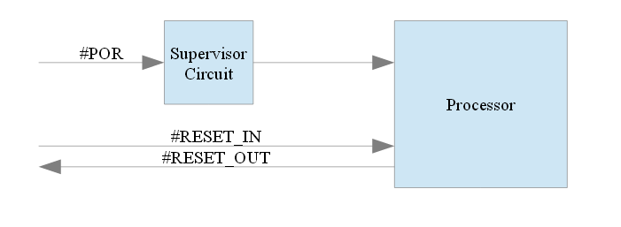
#RESET_OUT |
Reset Out – Reset carrier board peripherals #RESET_OUT may be used to reset peripherals on the carrier board. Depending on the module type this signal might be asserted automatically by a system reset, but can be controller by a GPIO function during runtime on all modules. |
VDDIO |
O |
|||
16 |
#POR |
Power On Reset - active low input signal. Typically a push button reset, pull low to force a reset. A supervisor circuit is used on the TX module to monitor the power supply. This device assert a processor system reset (POR_B) if the power supply falls outside the programmed threshold or a manual reset (#POR) is asserted externally. Leave open if not used. |
5V PU |
I |
|||
Module |
Remark |
||||||
TX28 |
The i.MX28 power-on reset is generated internally. If low the module power supply is disconnected. |
||||||
TX28S |
Not connected |
||||||
17 |
#RESET_IN |
Master Reset - external active low Schmitt trigger input signal. When this signal goes active, all modules (except the reset module, SDRAMC module, and the clock control module) are reset. The behaviour might depend on the processor, please refer to the processor reference manual for details. #RESET_IN is directly connected to the processors RESET_B pin. Pull or connect to VDDIO if not used. |
VDDIO |
I |
|||