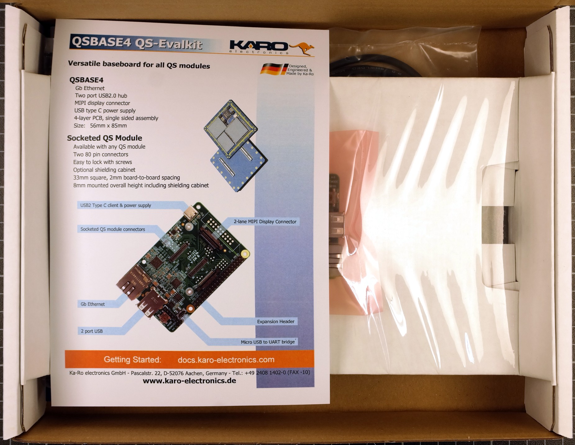
Quickstart Guide
This guide will help new users to quickly setup our QSBASE93 Linux Development Kit.
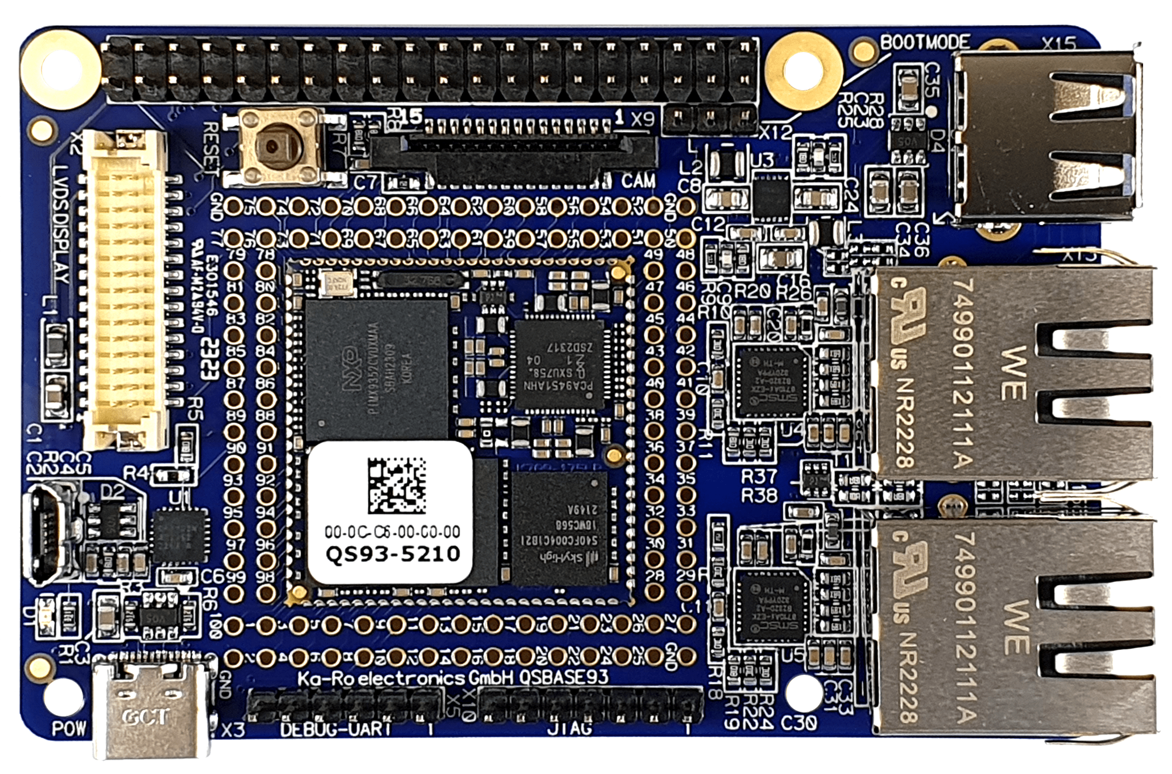
Detailed information about the QS93 solder-in module itself is available on our website.
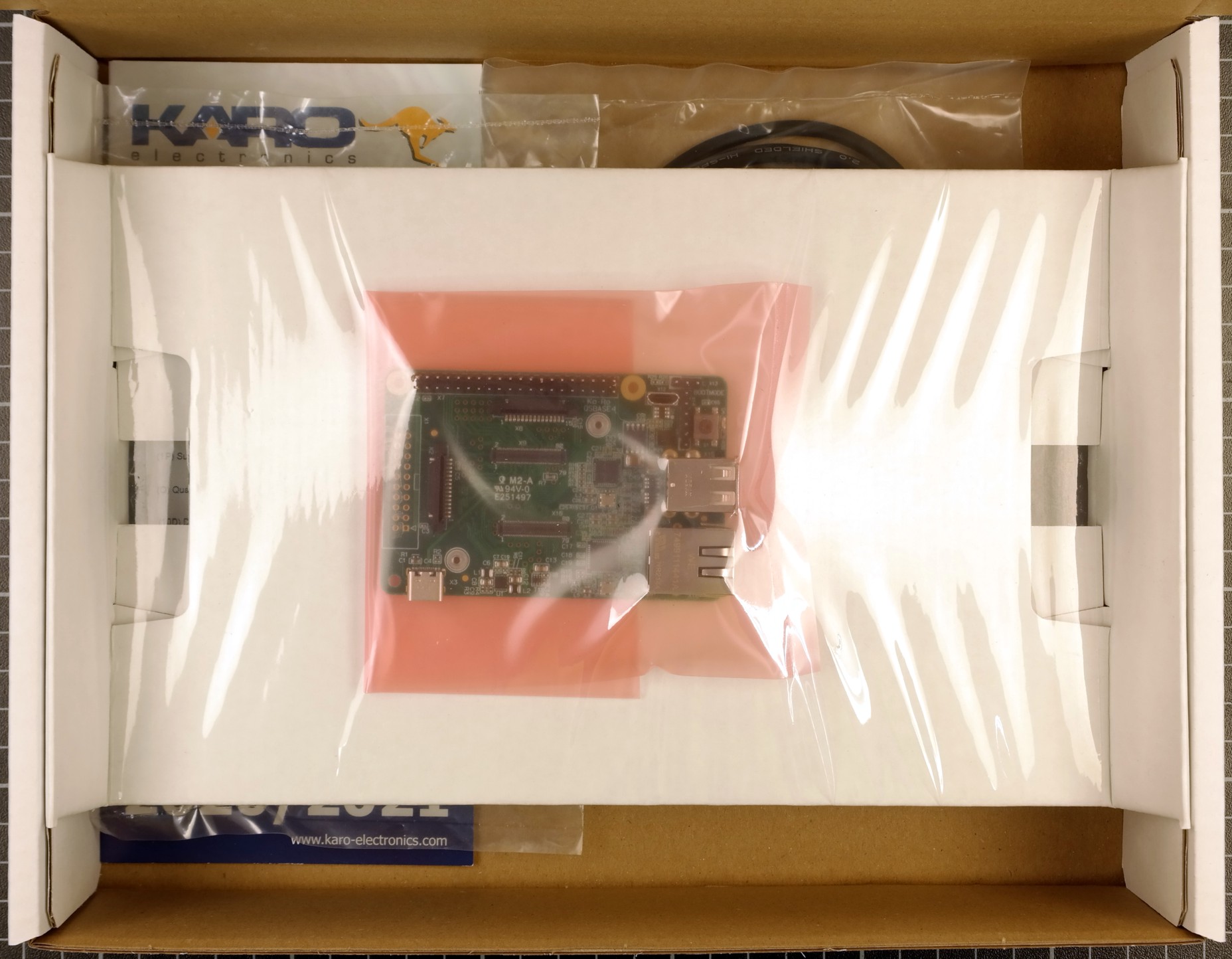
Unboxing
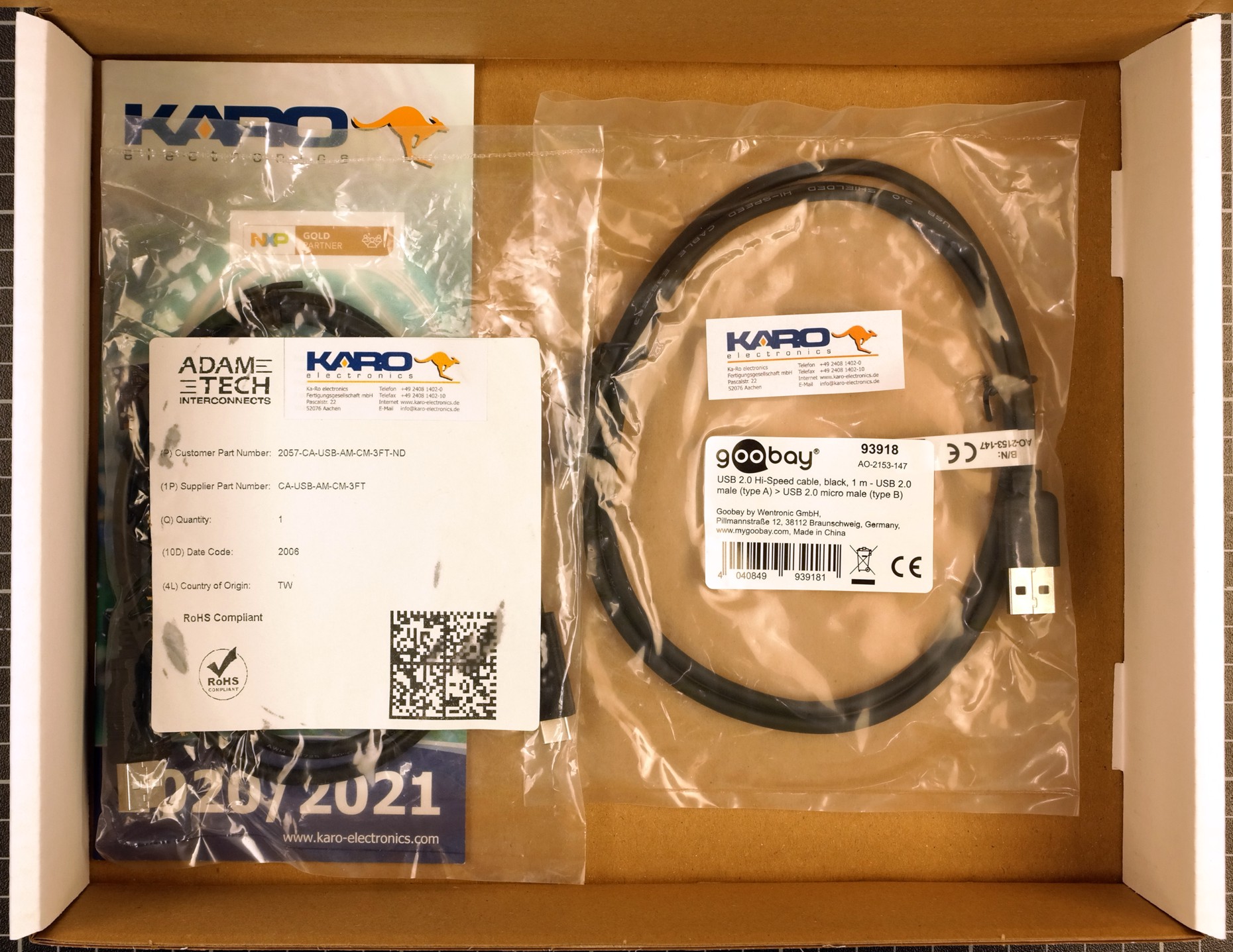
When opening the package of the Development Kit you should find the following components inside:
|
|
|
|
|
|
Wiring
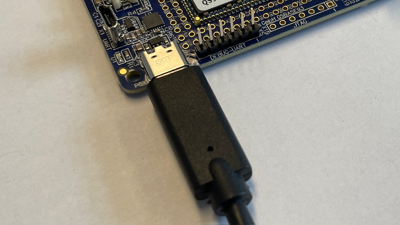
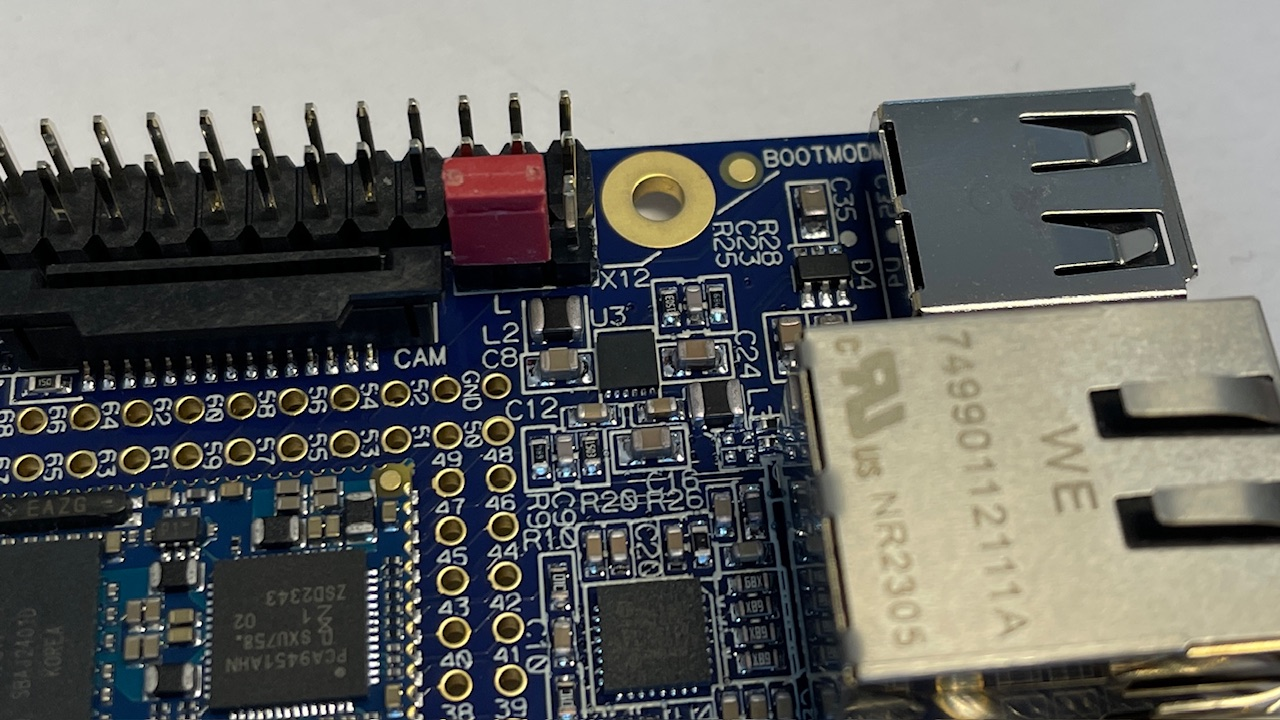
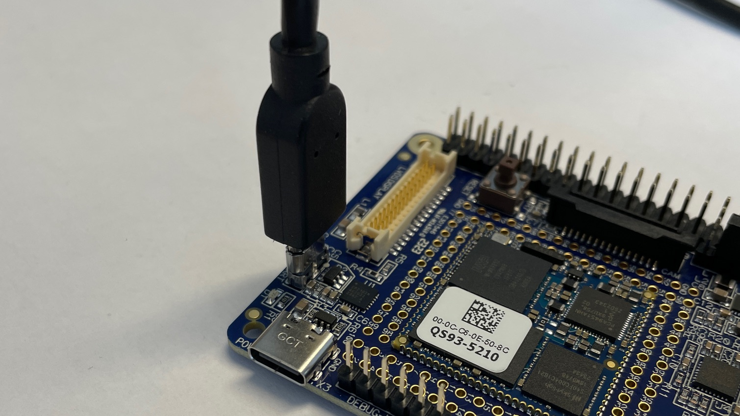
Connect the QSBASE93 board as shown in the image below.
|
|
|
This USB connection is used for both power supply and programming. |
This USB connection is used for the terminal |
|
|
|
|
The board may require more current than a standard USB 2.0 port can deliver. |
USB-UART driver
Download and Install USB to UART Bridge Virtual COM Port (VCP) drivers
Booting
After connecting the power supply your board will boot.
Your module is pre-programmed with our karo-image-minimal headless Linux.
Next Steps Usage
Topic |
Description |
|---|---|
Re-installing the OS |
|
Display support |
The QSBASE93 Development Kit supports different LVDS displays. We also provide a Ready To Use weston image to flash your QS module in our Download Area. |
Next Steps Software
Topic |
Description |
|---|---|
Linux Guide |
Go to: Software Documentation |
WiFi Guide |
To enable WiFi support. Go to: Software Documentation -> WiFi/BT Guide |
Machine Learning |
Using NPU and starting ML Demos. Go to: Software Documentation -> Machine Learning Guide |
QT6 Development |
Develop a QT6 app for your customers. Go to: Software Documentation -> QT Guide |
Electron Development |
Develop an Electron app for your customers. Go to: Software Documentation -> Electron Guide |
Customizing the BSP |
If you want to use our Yocto Layer, or want to create your own customized Linux distribution, have a look at our Yocto Guide. Go to: Yocto Guide |
Next Steps Hardware
Topic |
Description |
|---|---|
QSBASE93 Pinouts |
Connector pinouts can be found in the Hardware Documentation. Go to: Hardware Documentation -> Pinouts -> Pinout |
QS Developers Guide |
QS-Standard pinout, description and layout guidelines. Go to: Hardware Documentation -> QS-GUIDE |