I2C
Pin |
Signal |
Description |
type |
I/O |
|
|---|---|---|---|---|---|
40 |
I2C_DATA |
I2C Data |
VDDIO |
I/O |
|
41 |
I2C_CLK |
I2C Clock |
VDDIO |
O |
|
Module |
Devices connected to this I2C bus |
||||
TX25, TX27, TX28S, TX51, TX53, TX6 |
No devices are connected to this I2C bus. No pullup’s are used on the module. |
||||
Name |
Type |
Speed [kbps] |
Address |
||
TX28 |
DS1339 |
RTC |
400 |
1101000 r/w |
|
PCA9554 |
IO |
400 |
0100000 r/w |
||
TX48 |
DS1339 |
RTC |
400 |
1101000 r/w |
|
LTC3589 |
PMIC |
400 |
0110100 r/w |
||
The I2C is a two-wire, bidirectional serial bus that provides a simple, efficient method of data exchange, minimizing the interconnection between devices. This bus is suitable for applications requiring occasional communications over a short distance between many devices. The flexible I2C allows additional devices to be connected to the bus for expansion and system development.

Example I2C Voltage Level Translator (TX27 and TX51 only)
The Texas Instruments PCA9306 allows bidirectional voltage translations between 1.2V and 5V, without the use of a direction pin.
Be aware of the PCA9306 min. supply voltage: VREF2 > VREF1 + 0.6V. Because of this limitation a Texas Instruments TXS0102 should be used instead if the design is intended to be used with 1.8V and 3.3V TX modules.
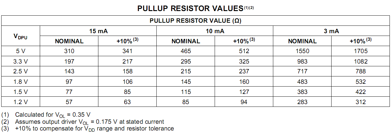
As with the standard I2C system, pullup resistors are required to provide the logic high levels on the translator’s bus. The PCA9306 has a standard open-collector configuration of the I2C bus. The size of these pullup resistors depends on the system, but each side of the repeater must have a pullup resistor. The device is designed to work with standard-mode and fast-mode I2C devices, in addition to SMBus devices. Standard-mode I2C devices only specify 3 mA in a generic I2C system where standard-mode devices and multiple masters are possible. Under certain conditions, high termination currents can be used.

I2C recommendations [2]
Recommendation |
Explanation |
|---|---|
Verify the target I2C interface clock rates. |
The bus can only operate as fast as the slowest peripheral on the bus. If faster operation is required, move the slow devices to another I2C port. A slow peripheral may unpredictably take over the bus or might malfunction in some other way. |
Verify that the target I2C address range is supported and does no conflict with other peripherals. If there is an unavoidable address conflict, move the offending device to another I2C port. |
If it is undesirable to move a conflicting device to another I2C port, review the peripheral operation to see if it supports remapping the address. |
Do not place more than one set of pullup resistors on the I2C lines |
This can result in excessive loading. Good design practice is to place one pair of pullups only. |