Engineering Boot Mode Details
Boot modes
STM32MP processors provide several sources to boot from. A set of jumpers selects the boot source after reset:
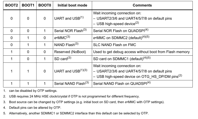
supported boot sources by STM32MP processors
The engineering boot mode is the Reserved mode (4) listed in the table above.
Situation on the QSMP module
The following extract from the module schematics shows the wiring of the boot mode signals:
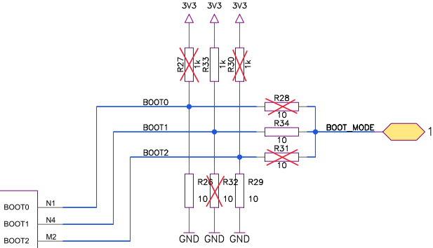
on-board wiring of the bootmode signals
BOOT0: pull down
BOOT1: pull up with external boot jumper to GND
BOOT3: pull down
With the jumper connected to the BOOT_MODE pin, it is possible to select between mode=0 (USB) or mode=2 (eMMC).
To switch to the engineering boot mode, you have to remove the pulldown from BOOT2 (R29) and have to solder pullup R30 and pull BOOT1 to GND with the boot jumper.
To identify these components on the board, see the following plan:
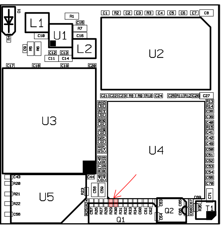
components layout of QSMP module
Unfortunately, these two resistors reside between the crystal (Q1) and the processor (U4). Due to the tight space on the board, the modification is very difficult.
important
That’s the reason, why Ka-Ro advise customers who need the engineering boot mode to switch to the TXMP module for development.
Situation on the TXMP module
The TXMP-module provides isolated resistors on the module edge, that are relatively easy to change:
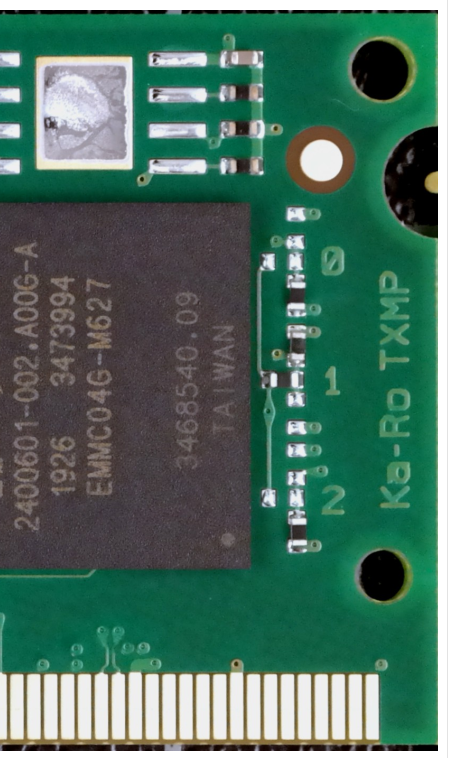
components layout of TXMP module
Please note, the boot signals are labeled in copper.