Enabling USB-Bootmode
The Boot from USB Mode, or sometimes called Download Mode, is necessary to change the operating system on your board. In this mode you’re able to flash the bootloader, eMMC or NAND with manufacturing tools.
QS(X) Modules
Module |
Boot from USB/UART |
Boot from eMMC/NAND |
|---|---|---|
QS8M-* |
Connect to high (H) |
Leave open or low (L) |
QSXM-* |
Connect to high (H) |
Leave open or low (L) |
QSXP-* |
Connect to high (H) |
Leave open or low (L) |
QSRZ-* |
Connect to high (H) |
Leave open or low (L) |
QS93-* |
Connect to high (H) |
Leave open or low (L) |
QSMP-* |
Connect to low (L) |
Leave open or high (H) |
TX Modules
Module |
Boot from USB/UART |
Boot from eMMC/NAND |
|---|---|---|
TX* |
Connect Bootmode Pins (L) |
Leave open (H) |
Physical Pins
QSBASE1
The 3 bootmode pins are located next to the RGB display output. With the jumper the bootmode can be set to high (H) or low (L).

QSBASE1 Bootmode Pins
QSBASE2
The 3 bootmode pins are located below the Raspberry Pi-Connector, next to the CAMERA input. With the jumper the bootmode can be pulled to high (H) or low (L).

QSBASE2 Bootmode Pins
QSBASE3
The 3 bootmode pins are located next to UART A. With the jumper the bootmode can be pulled to high (H) or low (L).

QSBASE3 Bootmode Pins
QSBASE4
The 3 bootmode pins are located next to UART A. With the jumper the bootmode can be pulled to high (H) or low (L).

QSBASE4 Bootmode Pins
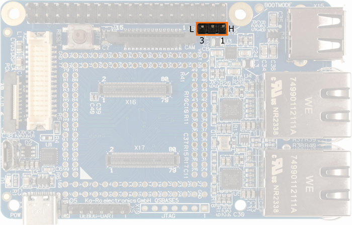
QSBASE5
With the jumper the bootmode can be pulled to high (H) or low (L).

QSBASE5 Bootmode Pins
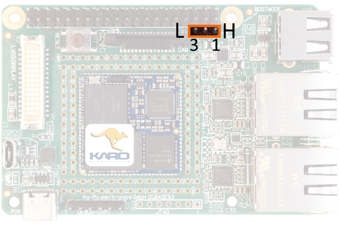
QSBASE93
With the jumper the bootmode can be pulled to high (H) or low (L).

QSBASE93 Bootmode Pins
TX-(MIPI)-LVDS Mainboard
To bring your device into USB Boot Mode, place a jumper to connect the Boot Mode pins.
For normal boot, please check that the bootmode jumper is open.

Boot Mode jumper in place
JP1 is used to configure the boot mode and the JTAG topology.

JP1 pin mapping
There is only one JTAG on the chip, and two JTAG modes are supported. Between these modes is selected via the JTAG_MOD pin:
Mode |
JTAG_MOD |
Function |
|---|---|---|
Debug mode |
0 |
DAP is the only TAP controller in the daisy chain. SJC will be attached to JTAG-AP of DAP. |
Test mode |
1 |
SJC is the only TAP controller in the daisy chain. 1149.1-compliant, and support 1149.6 AC coupled test. |
Do not connect the TEST_MODE pin!
TX Mainboard 7
To bring your device into USB Boot Mode, place a jumper to connect the Boot Mode pins.

MB7 Bootmode
TXUL EvalKit
To bring your device into USB Boot Mode, place a jumper to connect the Boot Mode pins.

TXUL EvalKit Bootmode