QSBASE4
This guide will help new users to quickly setup our QSBASE4 Linux Development Kit.
Detailed information about the QS solder-in module itself is available on our website.
Unboxing
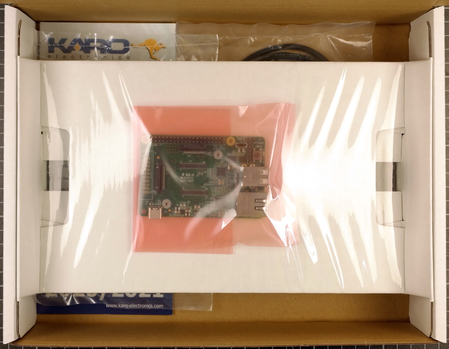
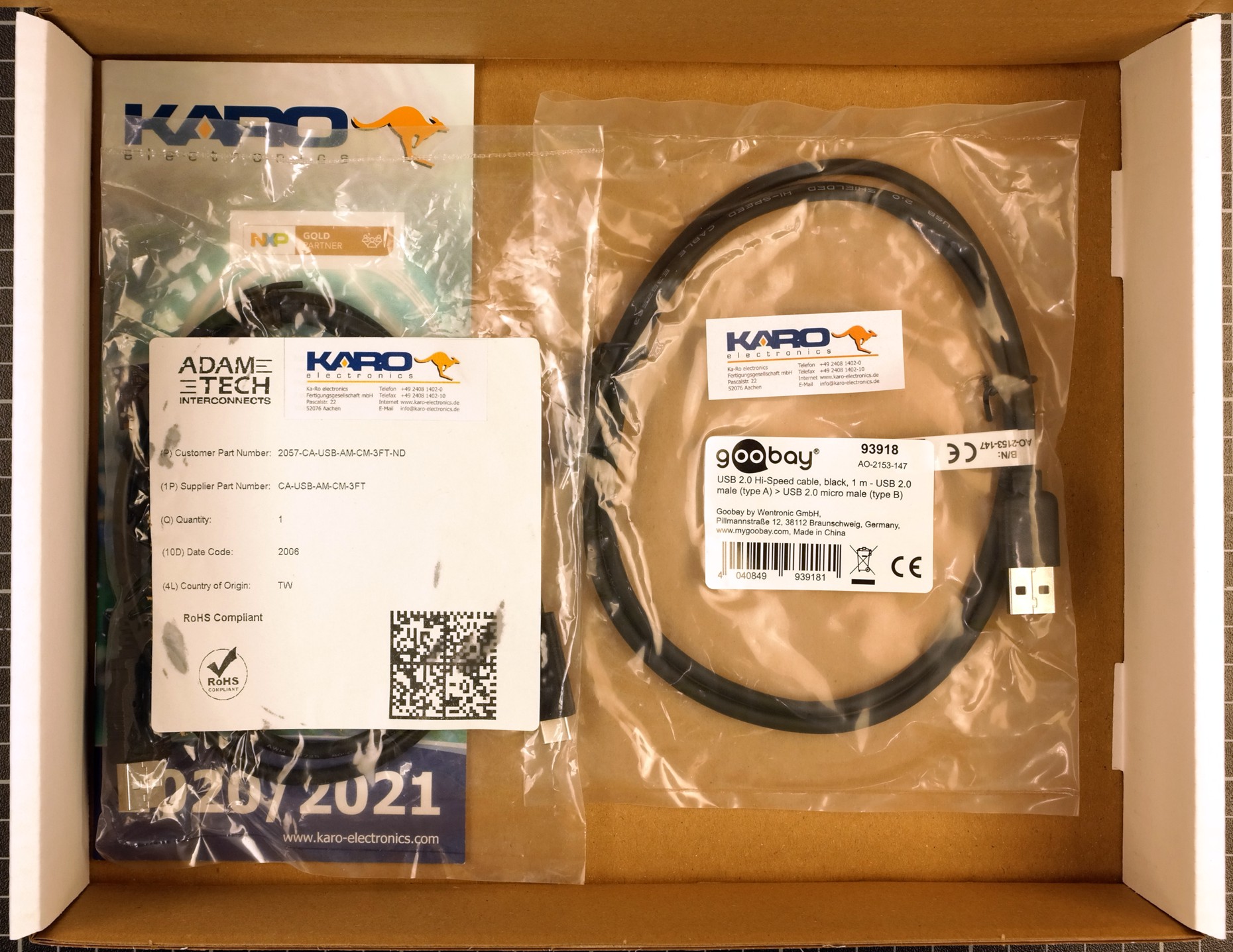
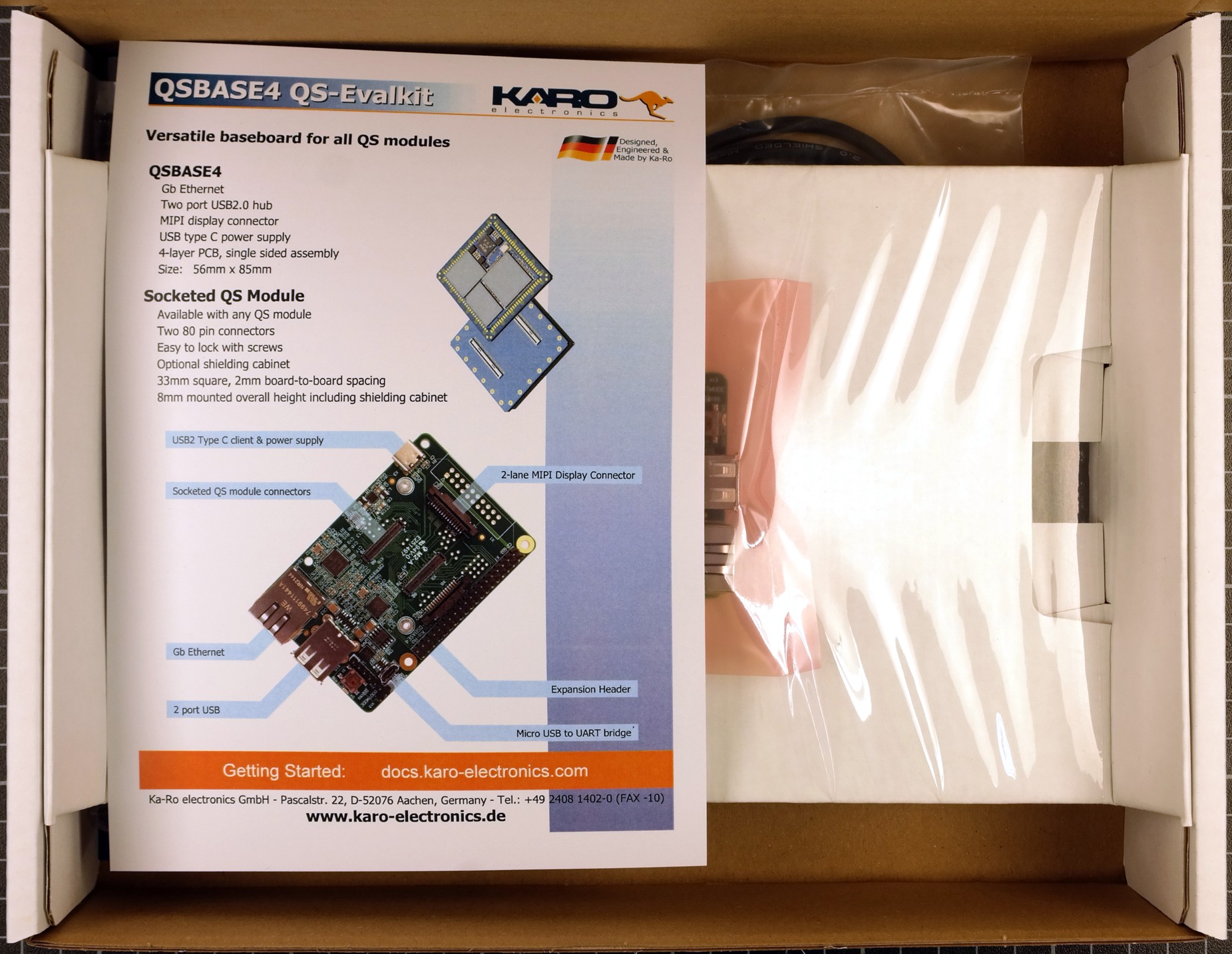
When opening the package of the Development Kit you should find the following components inside:
|
|
|
|
|
|
Wiring
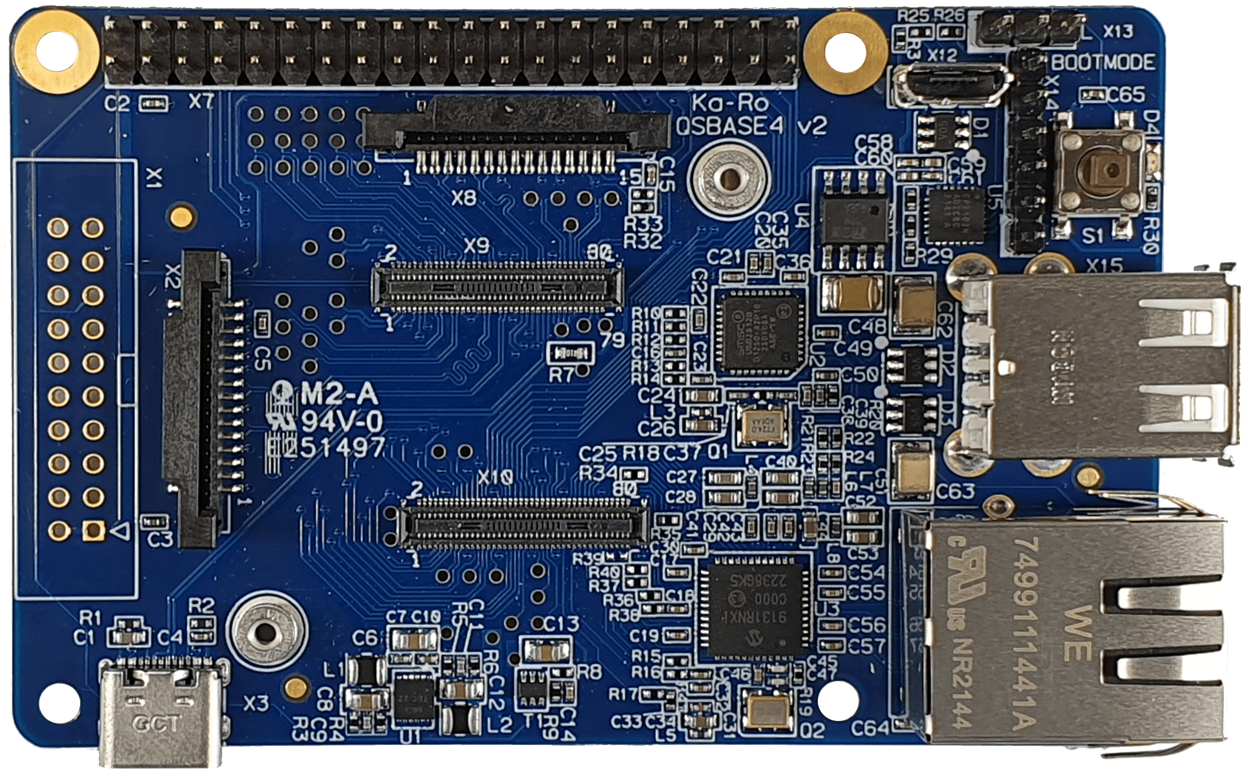
Connect the QSBASE4 board as shown in the image below.
|
|
|
This USB connection is used for both power supply and programming. |
This USB connection is used for the terminal |
|

|

|

|
The board may require more current than a standard USB 2.0 port can deliver. |
USB-UART driver
Download and Install USB to UART Bridge Virtual COM Port (VCP) drivers
Booting
After connecting the power supply your board will boot.
U-Boot 2020.04-5.4.24-2.1.0+g603345d2df (Oct 12 2020 - 10:42:27 +0000)

[...]

Hit any key to stop autoboot:  0
14753800 bytes read in 340 ms (41.4 MiB/s)
## Flattened Device Tree blob at 43000000
   Booting using the fdt blob at 0x43000000
   Loading Device Tree to 0000000062fef000, end 0000000062ffffff ... OK
serial-number: 2d70c9dd0002aaff

Starting kernel ...

[    0.000000] Booting Linux on physical CPU 0x0000000000 [0x410fd034]
[    0.000000] Linux version 5.4.47-2.2.0+g5ec03d06f54e (support@karo-electronics.de) (gcc version 9.2.0 (GCC)) #1 SMP PREEMPT Thu Nov 5 11:48:38 UTC 2020
[    0.000000] Machine model: Ka-Ro electronics QSXP-ML81 (NXP i.MX8MP) module on QSBASE3 baseboard
[    0.000000] earlycon: ec_imx6q0 at MMIO 0x0000000030890000 (options '115200')
[    0.000000] printk: bootconsole [ec_imx6q0] enabled
[    1.359142] imx-drm display-subsystem: no available port
INIT: version 2.88 booting
Initializing /var... Done.
Starting udev
ALSA: Restoring mixer settings...
INIT: Entering runlevel: 2
/usr/sbin/alsactl: load_state:1735: No soundcards found...
Configuring network interfaces... eth0: waiting for carrier
eth0: carrier acquired
DUID 00:01:00:01:c7:92:bd:1f:00:0c:c6:88:ea:90
eth0: IAID c6:88:ea:90
eth0: adding address fe80::15a7:3b6e:6744:d573
ipv6_addaddr1: Operation not supported
eth0: soliciting an IPv6 router
ipv6nd_startrs1: Address family not supported by protocol
eth0: soliciting a DHCP lease
eth0: offered 192.168.0.21 from 192.168.1.1
eth0: probing address 192.168.0.21/23
eth0: leased 192.168.0.21 for 72000 seconds
eth0: adding route to 192.168.0.0/23
eth0: adding default route via 192.168.1.90
forked to background, child pid 1669
done.
Starting system message bus: dbus.
Starting rpcbind daemon...done.
Starting ntpd: done
Starting syslogd/klogd: done

karo-minimal (Ka-Ro Linux BSP with minimal read-only rootfs) 5.4-zeus qsxp-ml81 /dev/ttymxc0

qsxp-ml81 login:
Your module is pre-programmed with our karo-image-minimal headless Linux.
Nonfunctional
Note!
Missing features on some QS modules
Module |
Remark |
Nonfunctional interfaces |
|---|---|---|
QS93 |
No MIPI DSI |
Display |
QS91 |
No MIPI DSI |
Display |
QSMP-25 |
No MIPI DSI |
Display |
QSMP-23 |
No MIPI DSI |
Display |
QSMP-13 |
No MIPI DSI |
Display |
QSMP-1510 |
No MIPI DSI |
Display |
QS8M-ND00 |
Only one USB port |
USB Hub / Two USB Host connectors |
Next Steps Usage
Topic |
Description |
|---|---|
Re-installing the OS |
|
Display support |
The QSBASE4 Development Kit supports the official Raspberry Pi 7inch Touch Display. The QSBASE4 can be mounted directly to the display. Tip The official Product Site of the Raspberry Pi 7inch Touch Display: https://www.raspberrypi.org/products/raspberry-pi-touch-display/ The sources supporting the Display are integrated our Yocto Layer. Refer to our Yocto Guide. We also provide a Ready To Use weston image to flash your QS module in our Download Area. 

|
Next Steps Software
Topic |
Description |
|---|---|
Linux Guide |
Go to: Software Documentation |
WiFi Guide |
To enable WiFi support. Go to: Software Documentation -> WiFi/BT Guide |
Camera Guide |
To enable camera support. Go to: Software Documentation -> Camera Guide |
Google Coral Edge TPU |
How to use Google Coral PCIe ML accelerator. Go to: Software Documentation -> Coral Edge TPU |
Machine Learning |
Using NPU and starting ML Demos. Go to: Software Documentation -> Machine Learning Guide |
QT5 Development |
Develop a QT5 app for your customers. Go to: Software Documentation -> QT Guide |
Electron Development |
Develop an Electron app for your customers. Go to: Software Documentation -> Electron |
Customizing the BSP |
If you want to use our Yocto Layer, or want to create your own customized Linux distribution, have a look at our Yocto Guide. Go to: Yocto Guide |
Next Steps Hardware
Topic |
Description |
|---|---|
QSBASE4 Pinouts |
Connector pinouts can be found in the Hardware Documentation. Go to: Hardware Documentation -> Pinouts -> QSBASE4 |
QS Developers Guide |
QS-Standard pinout, description and layout guidelines. Go to: Hardware Documentation -> QS-GUIDE |