TX MIPI-LVDS StarterKit
This guide will help new users to quickly set up our TX MIPI-LVDS Linux Development Kit.
Detailed information about the TX modules are available at https://www.karo-electronics.com/products .
Unboxing
When opening the package of the Development Kit you should find the following components inside:
Our catalog and the TX datasheet.

A 10.1” or 7” capacitive touch display with 1280x800 resolution.

A micro USB cable for programming.

A small plastic bag with cables for connecting the display and its touchscreen.
A TTL to USB Serial Converter cable.

The development board with the TX module already plugged into it.
An AC / DC 12V wall adapter power supply.
A display stand.

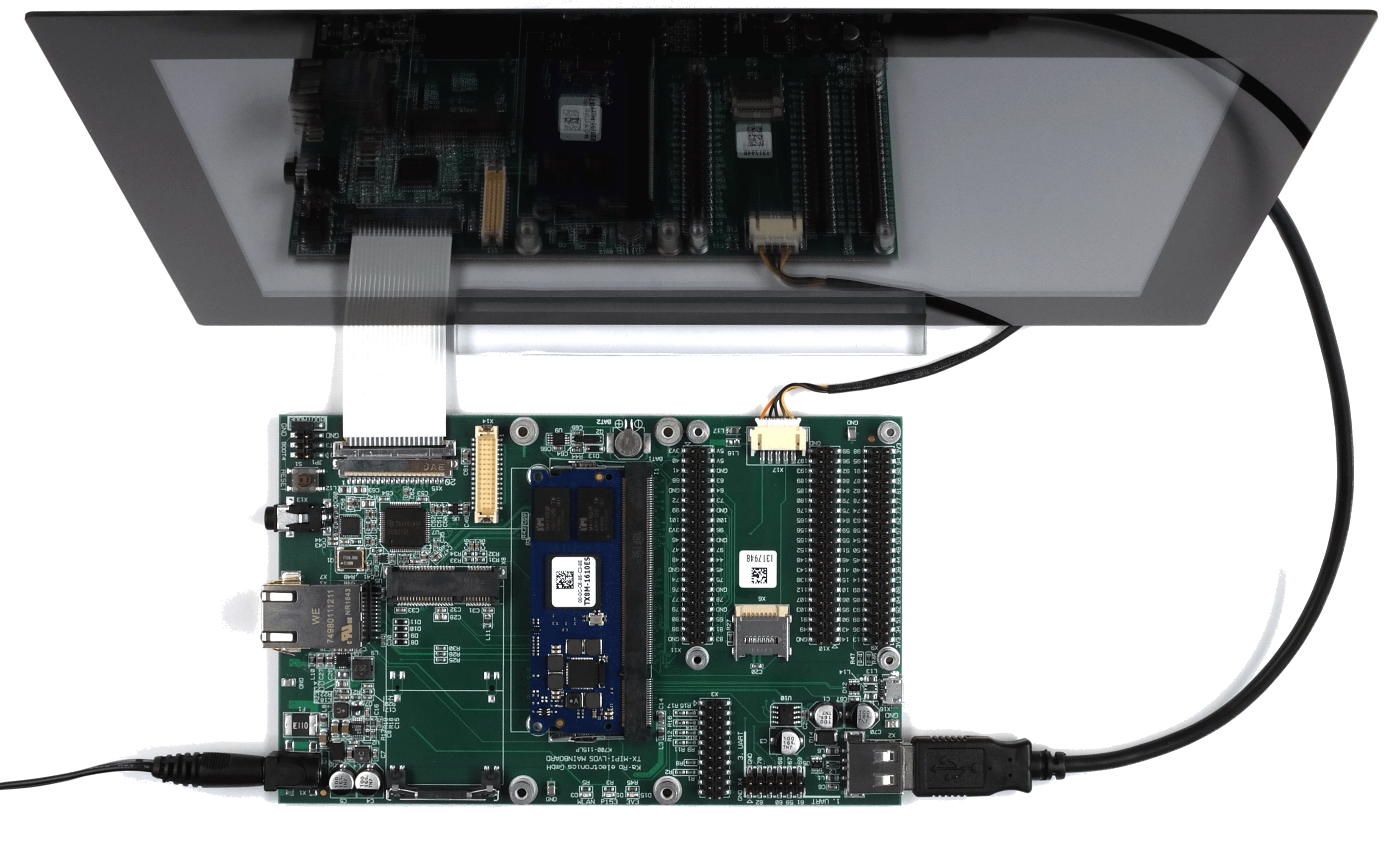
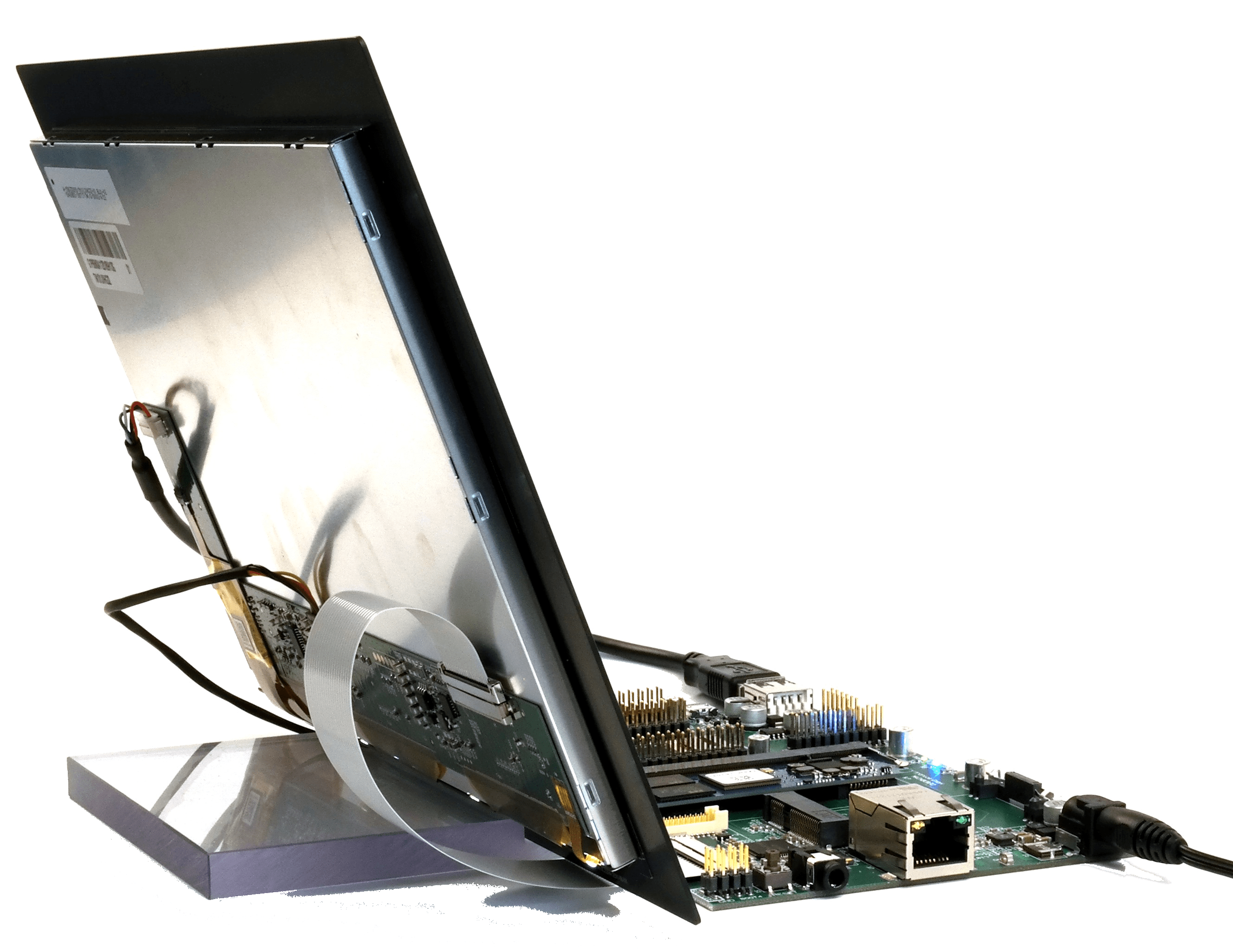
Assembling and Connecting
Assemble and connect the board to the display as shown in the following pictures. This means:
Connect the display powering between board power outlet and displays power input.
Connect the touchscreen to USB cable between the displays port and the USB-host port of the board.
Carefully connect the display signal cable.
Place the display on the stand and place the board in front of it.
As the last step connect the 12V DC power and plug the AC adapter into your powerline.
Warning
Please be careful, it’s highly recommended to disconnect the 12V power before (un)plugging the module or other cables.
Hint
When you have the TX8M-ND00 module, you will have to use the micro-USB to USB adapter to connect the touchscreen. The second USB-host is not working with the i.MX8M Nano processor.
Terminal Connection
Use the TTL to USB Serial Converter cable to connect your computer with the board via 1. UART. The black wire goes to “GND”-Pin.
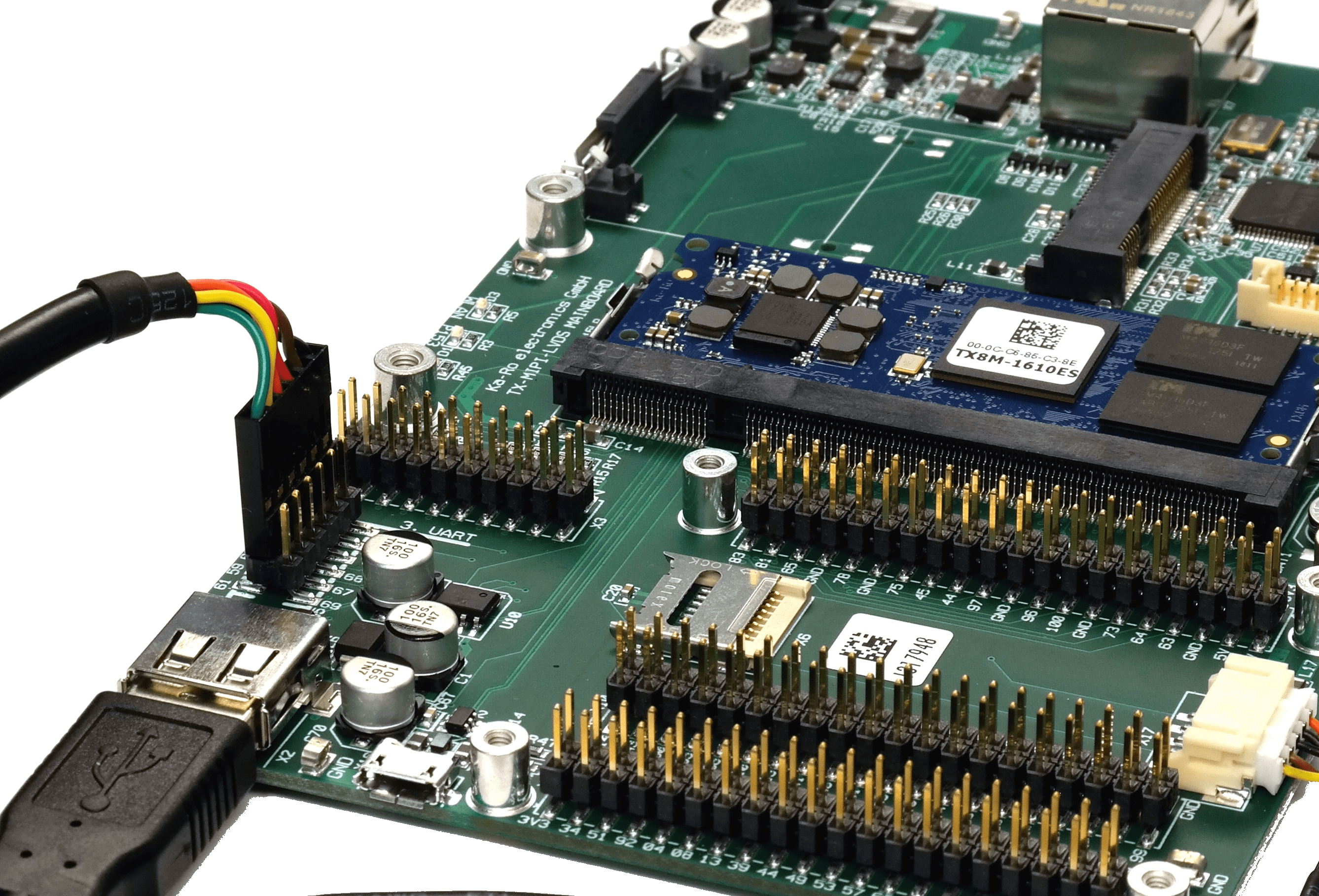
UART connection to serial USB cable
To open the terminal connection see our FAQ: TTL Converter Terminal Connection.
Booting
After connecting the 12V power your Development Kit will boot a Weston desktop - ready to use.
Next Step Usage
Topic |
Description |
|---|---|
Re-installing the OS |
|
CAN support |
If you want to use a CAN interface via the Raspberry Pi-Connector on the TX-MIPI-LVDS, you have to enable CAN inside the compiled With using this DTB, the CAN interface via SPI gets activated for you, and you should be able to set up the device as an interface. Notice the placing of the CAN interface: For an exact pinout see the X11 Header in TX-MIPI-LVDS Mainboard Pinout. 
MCP2515 CAN interface¶ |
Next Step Software
Topic |
Description |
|---|---|
Linux Guide |
This guide refers to the use of images built with Yocto NXP BSP. Go to: Software Documentation -> TX8 -> NXP BSP |
Machine Learning (TX8P only) |
Using NPU and starting ML Demos. Go to: Software Documentation -> TX8P -> Machine Learning Guide |
QT6 Development |
Develop a QT6 app for your customers. Go to: Software Documentation -> TX8 -> QT Guide |
Electron Development |
Develop an Electron app for your customers. Go to: Software Documentation -> TX8 -> Electron |
Customizing the BSP |
If you want to use our Yocto Layer, or want to create your own customized Linux distribution, have a look at our Yocto Guide. Go to: Yocto Guide |
Next Step Hardware
Topic |
Description |
|---|---|
TX-(MIPI)-LVDS Pinouts |
Connector pinouts can be found in the Hardware Documentation. Go to: Hardware Documentation -> Pinouts -> TX-MIPI-LVDS Mainboard |
TX Developers Guide |
TX-Standard pinout, description and layout guidelines. Go to: Hardware Documentation -> TX-GUIDE |